sketchy outline shader
16 Nov 2024I may or may not have been distracted for absolutely forever, but time for a new post!
This time, I’ll talk about a shader I made for a music video ages ago. It is a shader that renders the scene with a wireframe mesh. However, unlike most wireframe shaders, I make the wireframe look hand-drawn. The following mineshaft scene was rendered fully with this shader (though I edited the colours in post to fit this blog):
In this post, I’ll introduce everything you need to do this yourself, from the ground up. Buckle up, this’ll be a long ride. (People that are already familiar with shaders can skip ahead to the “How to sketch, intuitively” section.)
The code for this shader as used in the video can be found in my pile-of-shaders repo. The code here will differ a little, for presentation purposes.
Shader crash-course: pixels
Back before GPUs were a thing, and before “shader” was a scary word, drawing graphics was just something you did on the CPU, like anything else. There was some block in memory where you wrote your frame data, which would be read by whatever was responsible for actually putting stuff on the screen.1
In other words, if you wanted to render a single 3D sphere, your code would probably look something like this.
for (int y = 0; y < WIDTH; y++) {
    for (int x = 0; x < HEIGHT; x++) {
        // CODE THAT CALCULATES THE COLOUR OF (x,y).

        // First determine whether this pixel is actually part of
        // your sphere. Then do some physics to colour it properly.
        return CalculateColor(x,y);
    }
}
In this case, the only intimidating thing, really, would be the contents of CalculateColor(x,y) – the math for rendering a sphere. You wouldn’t have to deal with the entire separate framework of “shaders” that seems to intimidate people.
However, this is pretty slow. Pixel by pixel computation may be feasible when you’re rendering tens of thousands of pixels, but you wouldn’t render the millions of pixels of today’s screens like that. You’re executing the same code for each pixel, and only the x and y variables are different. What if you had a device that could, say, do the same shading code on thousands of pixels at a time?
This is the task of the GPU. Compared to your CPU, it executes fewer instructions per second, and handles code with conditionals very poorly. But in exchange, we get the upside of massively parallelizing our execution.
color frag(float2 xy : TEXCOORD) : SV_Target {
    // CODE THAT CALCULATES THE COLOUR OF (x,y).
    // This is run for every pixel; the double for-loop above
    // is implicit now.

    // First determine whether this pixel is actually part of
    // your sphere. Then do some physics to colour it properly.
    return calculate_color(xy);
}
This “fragment shader” is run for every pixel2, and (sort-of) at the same time. We don’t need to worry about the manual double for-loop as in the CPU case, as that’s abstracted away now.
However, shaders don’t just do pixels.
Shader crash-course: vertices
While GPUs are pretty good at the 2D stuff, that’s not really their main focus. They really shine in 3D.
Consider our previous hard-coded sphere program. What if we wanted to add another sphere? What if we wanted to move the two around? The approach above quickly becomes awkward when you keep adding stuff to your scene.
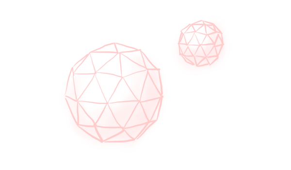
The way the modern graphics pipeline solves this, is to work with geometry, first and foremost. The GPU accepts a list of triangles that represent various objects, and renders those. In our case, we approximate the two spheres with a pile of triangles.
The GPU first lets you modify of these triangles’ corners, the vertices, in the “vertex shader”. Move them around, make them do a little dance, you can do whatever you want. This is usually where the math happens that makes “cameras” and “perspective” a thing in 3D engines. After that, the GPU executes the “fragment shader” for every triangle, for every pixel that lies on that triangle. Our code that renders these spheres will now look something like this. (I’m still not gonna include any math yet.)
fragment_input vert(vertex_input vertex) {
    // Do some math so that this triangle vertex takes into account
    // perspective and perhaps some other stuff.
}

color frag(fragment_input fragment) : SV_TARGET {
    // CODE THAT CALCULATES THE COLOUR OF `fragment.xy`.
    // This is run for every triangle for every pixel inside that
    // triangle, and returns the colour on your screen.
}
The GPU abstracts away quite a lot for us. If you wanted to do this on the CPU, you’d get a ton of loops!
// Vertex calculations
foreach(var vertex in triangle_vertices) {
    // Do some math so that this triangle vertex takes into account
    // perspective and perhaps some other stuff.
}

// Fragment calculations, using the modified positions
foreach(var triangle in triangles) {
    foreach (var fragment in triangle) {
        // CODE THAT CALCULATES THE COLOUR OF `fragment.xy`.
    }
}
And not only are all of these loops implicit, the GPU also executes them in parallel! Truly a wonderful little piece of hardware, isn’t it? This way, you can spend millions of triangles rendering thousands of teeth a player’s never gonna see, or detail each individual bristle on a tiny toothbrush, and people might not even notice!
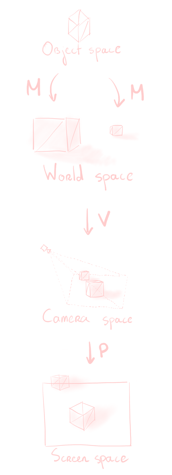
Various coordinate spaces
Okay, I want to avoid discussing mathematical concepts as much as I can in this post, but this is something I can’t get around. I’ll have to talk about coordinate spaces.
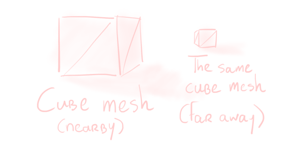
When you create 3D meshes in Blender or Maya or whatever, you (usually) create them near $(0,0,0)$. All triangles of your mesh are defined with respect to this origin. But when you want to put your mesh in a scene a kilometre over, you don’t move every single triangle in your mesh over. You would have to change every single vertex, which would take a lot of time. Instead, you separately store that you moved your mesh a kilometre over.
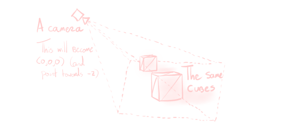
Then there’s the camera rendering your scene. The math for doing camera things (such as perspective) is much easier if the camera is at $(0,0,0)$. This requires us to move everything in the scene over! Again, you don’t store this movement in every triangle, or every object, for the same reason as before. You just store this in the camera.
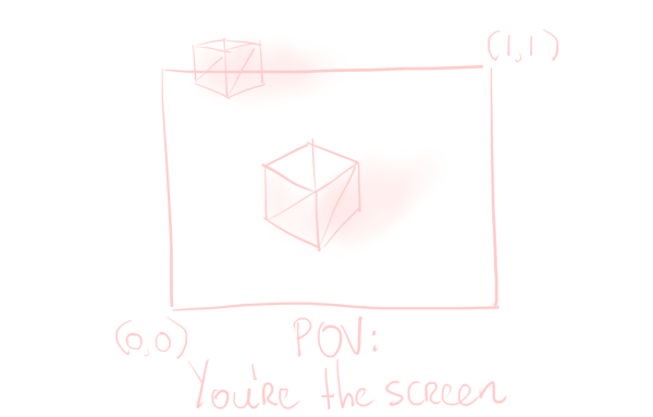
Finally, there’s the space that actually represents your screen. The left of your screen is at $x = 0$, the right of your screen is at $x = 1$, it’s pretty predictable behaviour3.
This leads us to define the following coordinate spaces.
- The object space puts the model at $(0,0,0)$. The three coordinates represent, respectively, “to the side”, “upwards”, and “forwards”4, compared to the model’s orientation.
- World space has an arbitrary origin denoted as $(0,0,0)$. Models, cameras, light sources, everything is positioned relative to this origin. The y-coordinate represents “up”, while the other two are the horizontal plane.
- Camera space puts the camera at $(0,0,0)$, pointing in the $-z$ direction.
- Screen space represents your screen5.
Converting between these spaces requires a bunch of linear algebra, but we’ll just be considering these transformations to be black boxes that we’ll call M, V, and P.
- To go from object space to world space, we apply the model matrix
M. You may also know this matrix as the transform of your object. - To go from world space to camera space, we apply the view matrix
V. This is the inverse of the camera’s transform. - To go from camera space to screen space, we apply the projection matrix
P. This matrix depends on your camera’s settings, and as its name suggests, also handles perspective projection.
We won’t have to worry about constructing these matrices ourselves, as Unity – the engine I’m using – will just give them to us.
A slightly more comprehensive explanation about these various coordinate spaces, with a very helpful animation, can be found here.
How to sketch, intuitively
Now that we know what shaders are, it’s time to get to business. But before we can get started with the code, we should know what we’re doing, first. What is it that we’re actually doing when I say we’re sketching?
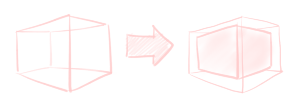
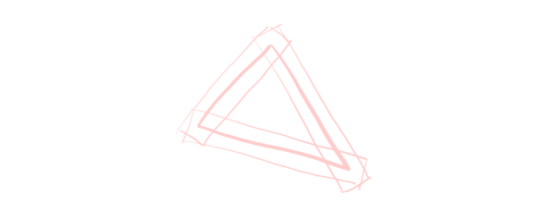
What I’m doing is conceptually quite simple really. For every triangle, I want to have a sketchy line on top of its three edges. To achieve this, we overlay a small rectangle (i.e. two triangles) over each of its edges, with a “line” texture on each of them.
Personally, I want my lines to be of consistent thickness throughout6. The easiest way to do this is to draw the lines “on the screen”. In other words, we’ll need to generate our triangles in screen space.
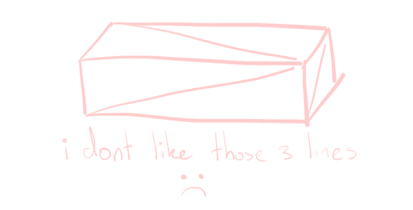
This approach would also create diagonal lines for cuboids like pillars and rails I would have in my scene. I don’t want these lines, as they break up the scene.
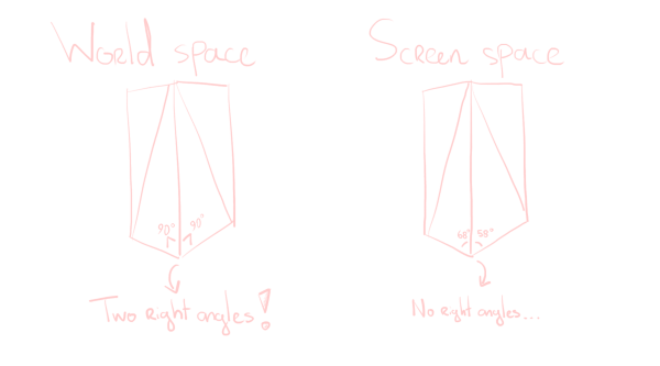
The way we go about preventing them is checking for right angles. If two of the three edges of a triangle form a right angle, we simply don’t draw the third. We cannot check for right angles in screen space however, as the perspective projection distorts angles – if you put a protractor physically on your screen, it won’t be a neat 90°!
So instead, we check for right angles in world space. (Object space and camera space would also work fine. I just want to use all spaces for this post.) We can even give some margin to this check, so that very tall, thin triangles don’t give a cluster of lines either. This improves the look of, for instance, the poles of UV spheres.
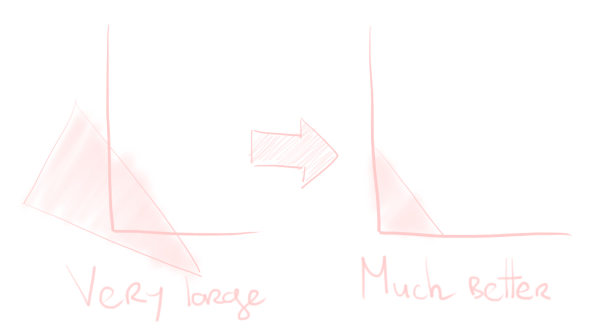
One thing I haven’t mentioned so far, is an optimization the GPU does for us: clipping. Suppose we have a triangle that lies only partially inside of screen space. We don’t want to spend effort rendering the pixels outside the screen, do we? Luckily, the GPU shrinks the triangle right into view.
Unfortunately – and I don’t know if this is hardware-dependent – the triangles we will add don’t get clipped automatically. We need to manually put in the effort to achieve the same effect. This is not so much a performance optimization, but a correctness optimization. (If you write a shader like this, you really can’t claim to care about performance!) You can get some really ugly artefacts otherwise if you fail to take this into account. For instance, lines that just zoom from one end of the screen to another, when they should’ve just been invisible!
Finally, we don’t want to see occluded lines. Up until now, I have not drawn the lines on the backside in my images for clarity. However, we’ve done nothing to guarantee that yet. Similarly, if some object is covering some other object’s lines, we want that “covering” behaviour properly. To solve this, we also render a shrunken-down version of the mesh, entirely the same colour as the background. This covers both the backside lines, and any object behind.
The “intuitive” explanation is quite long already, so putting this into code will be an adventure!
Occlusion
Let’s start with the last thing I discussed in the previous section, as it’s the easiest. It’s also a fun demonstration of how vertex shaders can do more than just transform into screen space.
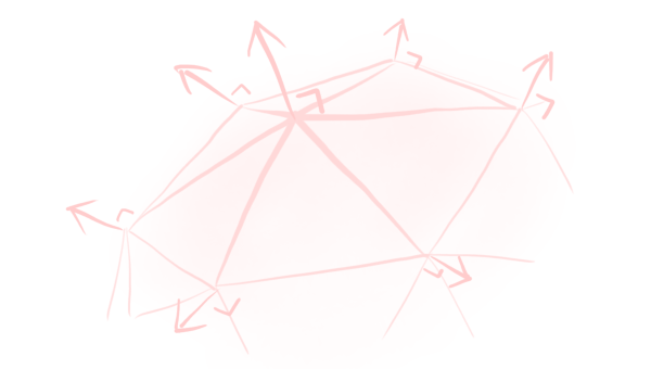
Let’s think about this “shrinkage”. The easiest way to go about this is to shrink our mesh in object space, before our other calculations. To do this, we need something called the “normal” vector. This is a vector that points away from the surface of the mesh, and is provided to us.
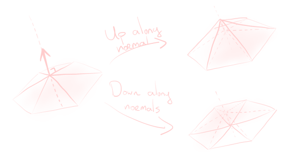
This vector is always of length one. Shrinking/expanding a mesh can now be described as “move vertices along their normal direction”.
The code to shrink is very easy now. We just move all vertices by offsetting them by a multiple of their normals. Afterwards, we need to do the “ordinary” rendering pipeline steps, and go from object space to screen space. This is then our vertex shader.
float4 vert (
    float4 object_space : POSITION,
    float3 normal : NORMAL
) : SV_POSITION {
    // Shrink the mesh along the normals
    object_space.xy -= 0.1 * normal;

    // Now convert our updated object to screen space.
    // (You could just use UNITY_MATRIX_MVP, but I want to emphasise
    //  the different spaces, because we're really going to be using
    //  them later!)
    float4 world_space = mul(UNITY_MATRIX_M, object_space);
    float4 camera_space = mul(UNITY_MATRIX_V, world_space);
    float4 screen_space = mul(UNITY_MATRIX_P, camera_space);
    return screen_space;
}
We want to render every pixel the same background colour. This gives us a very easy fragment shader, where we just return that colour.
float4 frag () : SV_TARGET {
    return float4(_InnerColor.rgb, 1);
}
The variable _InnerColor is the colour the end-user (me) sets in the Unity editor, and should be the same as the background colour. Fortunately, there’s no complex logic whatsoever to just rendering a solid colour!
Geometry shaders
(Un?)fortunately, now we get to the interesting and more difficult part. The pass above can be run, and then you have the shrunken monochromatic mesh. However, to do the line drawing, we don’t just need vertex and fragment shaders. They are not sufficient for creating triangles as discussed above. For this, we require a new kind of shader: the geometry shader.
The geometry shader is a shader that lives between the vertex and fragment shader steps, and as its name suggests, it’s used to modify geometry. You can use them to add or remove whatever you want!
However, in general, geometry shaders are kind of bad7, and if you really need more triangles, you’d best use “tessellation” shaders. However, the triangles I’m adding simply don’t mesh well with tessellation, so I don’t really have a choice8.
In pseudocode, you can think of geometry shaders as follows:
List<Triangle> newGeometry;
foreach (var triangle in oldTriangles) {
    // Calculate new triangles based on this triangle.
    // Then add these triangles into the `newGeometry` list.
}
In hlsl proper, they look like this.
// This tells the GPU: Every triangle we processes will result in at
// most 12 new vertices.
[maxvertexcount(12)]
void geom(
    triangle vertex_output IN[3],
    inout TriangleStream<fragment_input> triStream
) {
    // We get the three vertices the vertex shader gave us in `IN`.
    // Use this data to create new vertex positions v1, ..., vN.
    // Then add geometry by appending triangle strips:
    triStream.Append(v1);
    triStream.Append(v2);
    triStream.Append(v3);
    ...
    triStream.Append(vN);
    triStream.RestartStrip();
}
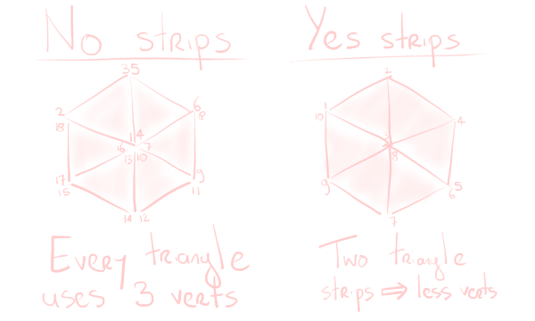
Triangle strips are a neat way to represent geometry more efficiently. After you specify your first triangle, each triangle afterwards is fully specified by just one point, which connects to the previous two points. This saves quite some duplication! Once we’ve decided we want to start somewhere else, we can simply restart the strip and continue somewhere else.
Creating lines
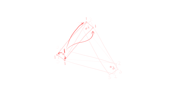
Now it’s time to start creating the lines we went through in the intuitive description. In our case, we will be creating three quads.
A quad is simply a triangle strip with four vertices. These three quads don’t connect neatly to each other (they even overlap!). As such, for each triangle in the mesh, we’ll be generating three triangle strips, for a total of 12 vertices. As mentioned earlier, we will be doing this in screen space, around each edge.
The three lines we want to make lie between each pair of vertices of the triangle. So we can simplify our problem by making a function draw_line() that creates a quad around a pair of vertices, and call that function three times.
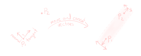
Because we’re working in screen space, we effectively only have the $x$ and $y$ coordinates to worry about. To create a quad around a pair of vertices $p_1$ and $p_2$, we will need the direction of the line between them (the “tangent”), and the line perpendicular to that (the “normal”). You can then use these to find the vertices of our quad.
These two vectors can be obtained by calculating tangent as normalize((float2)p2 - p1), and normal as tangent.yx * float2(-1,1). This gives us the two directions we need to create the quad on the screen.
// The g2f struct contains the output of the geometry / input of the
// fragment shader, with positional and uv data.

// This function is called from the geometry shader three times, where
// p1 and p2 are the camera space positions of two of the vertices of
// the triangle we're dealing with.
void draw_line(
    float4 p1,
    float4 p2,
    inout TriangleStream<g2f> triStream
) {
    // We'll need camera space later; for now, screen space suffices.
    p1 = mul(UNITY_MATRIX_P, p1);
    p1 /= p1.w;
    p2 = mul(UNITY_MATRIX_P, p2);
    p2 /= p2.w;

    float2 tangent = normalize((float2)p2 - p1);
    float2 normal = tangent.yx * float2(-1,1);
    // Use a configurable line thickness [0,1].
    tangent *= _Thickness * 0.5;
    binormal *= _Thickness * 0.5;

    g2f o;
    o.pos = p1 - tangent + binormal;
    o.uv = float2(0,0);
    triStream.Append(o);
    o.pos = p1 - tangent - binormal;
    o.uv = float2(1,0);
    triStream.Append(o);
    o.pos = p2 + tangent + binormal;
    o.uv = float2(0,1);
    triStream.Append(o);
    o.pos = p2 + tangent - binormal;
    o.uv = float2(1,1);
    triStream.Append(o);
    triStream.RestartStrip();
}
This is quite a lot of code, but it’s just a bunch of setup, and then outputting our quad’s corners, vertex by vertex9.
As we’re creating triangles with uvs, there’s a few things we need to watch out for. First, these triangles’ winding order should be correct. If backface-culling is enabled, triangles created the wrong way around simply won’t render. Then there’s the four uv-coordinates. If you don’t want your textures to be messed up, you better make sure these are correct as well!
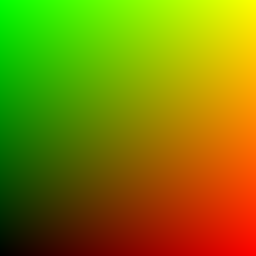
This is where I would put in some advice for figuring that out… Except that trial and error is just plain quicker. If the backface-culling is wrong and you can’t see anything, just swap the order of the vertices. If the uvs are wrong, just grab a texture that “prints” the coordinates like below, and you’ll immediately know what to do.
In this image, pixel $(x,y)$ has RGBA $(x,y,0,1)$, so that you can read off what’s going wrong by just looking at the colour. (If you’re not red-green colour blind, that is.)
Now we just call this draw_line() function in our geometry shader. We will assume that our vertex shader does nothing to our vertices for convenience, so that we start in object space10.
float4 vert(float4 vertex : POSITION) : SV_POSITION {
    return vertex;
}

[maxvertexcount(12)]
void geom(triangle vertex IN[3], inout TriangleStream<g2f> triStream) {
    float4 world_space[3];
    [unroll]
    for (int i = 0; i < 3; i++)
        world_space[i] = mul(UNITY_MATRIX_M, IN[i]);

    float4 camera_space[3];
    [unroll]
    for (int i = 0; i < 3; i++)
        camera_space[i] = mul(UNITY_MATRIX_V, world_space[i]);

    draw_line(camera_space[0], camera_space[1], triStream);
    draw_line(camera_space[1], camera_space[2], triStream);
    draw_line(camera_space[0], camera_space[2], triStream);
}
As mentioned in the intuitive sketch of this shader, we also don’t want the diagonal line you see on quads. To achieve this, we check whether two of the sides of the triangle have a dot product of (nearly) zero, and use this to decide whether to skip lines. We update our geom() function as follows.
[maxvertexcount(12)]
void geom(triangle vertex IN[3], inout TriangleStream<g2f> triStream) {
    ...

    float3 side1 = normalize((float3)world_space[1] - world_space[0]);
    float3 side2 = normalize((float3)world_space[2] - world_space[0]);
    float3 side3 = normalize((float3)world_space[2] - world_space[1]);

    // _DotRange is a user value that should be very close to zero.
    // The higher it is, the more angles are seen as "right", and the
    // more lines are not drawn. This may or may not be desirable.
    bool p0_is_right_angle = abs(dot(side1, side2)) < _DotRange;
    bool p1_is_right_angle = abs(dot(side1, side3)) < _DotRange;
    bool p2_is_right_angle = abs(dot(side2, side3)) < _DotRange;

    if (!p2_is_right_angle)
        draw_line(camera_space[0], camera_space[1], triStream);
    if (!p0_is_right_angle)
        draw_line(camera_space[1], camera_space[2], triStream);
    if (!p1_is_right_angle)
        draw_line(camera_space[0], camera_space[2], triStream);
}
Having significant branches like this in shaders is always painful, but as I said before, performance is not something I care very much about in this shader.
Clipping lines
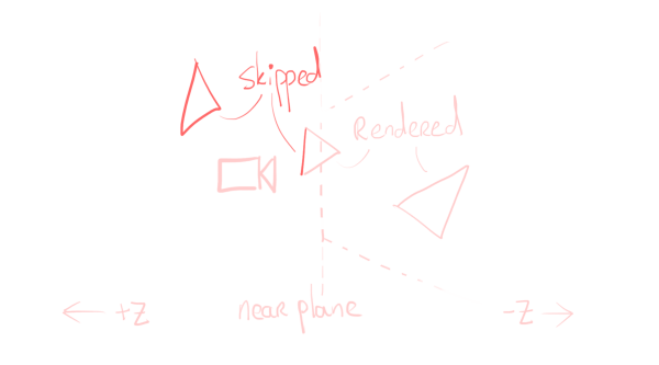
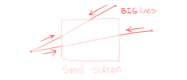
Unfortunately, the hardware does not clip our lines for us. If we accidentally put lines behind the camera, they will show up in front. If we make lines ten times as tall as the screen, we will get lines that look stretched out and only have 10% of the texture visible. These are not effects we want.
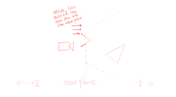
Checking whether we’re trying to create quads that are behind the camera, is a simple depth comparison. We just compare the two vertices with the near plane, and if both fall behind the camera, we won’t draw the line. If only one of them is behind the camera, we do draw the line.
In code, this is just a simple check.
bool3 in_view = float3(
    camera_space[0].z,
    camera_space[1].z,
    camera_space[2].z
) < near_plane;

if (!p2_is_right_angle && any(in_view.xy))
    draw_line(camera_space[0], camera_space[1], triStream);
if (!p0_is_right_angle && any(in_view.yz))
    draw_line(camera_space[1], camera_space[2], triStream);
if (!p1_is_right_angle && any(in_view.xz))
    draw_line(camera_space[0], camera_space[2], triStream);
However, even if we do this, we will still get stuff that’s behind the camera on the screen sometimes, if one point is in front and one point is behind. For this, we need to put in some more work and move points behind the camera to prevent this. We don’t want to change our lines, so we need to do this movement along the line they’re drawing. As we’re comparing whether we’re in front of or behind the camera, we’ll be working in camera space.
On paper, it looks simple, and mathematically, it is. Suppose $p_1$ is inside the frustum and $p_2$ is outside. We first calculate the direction vector tangent = p1 - p2, and then measure how many tangents we need to move $p_2$ to put it on the near plane:
void clip_near_plane(inout float4 p1, inout float4 p2) {
    // Proper code should use _ProjectionParams.y, but I was and am
    // lazy, apparently.
    float near_plane_z = -0.1;

    // Assume p1 is inside and p2 is outside. The other case is the
    // same of course.
    float4 tangent = p1 - p2;
    float dist = (near_plane_z - p2.z) / tangent.z;
    if (dist < 0)
        p2 = p2 + dist * tangent;
}
We can then use this in draw_line() before we compute screen space positions.
void draw_line(
    float4 p1,
    float4 p2,
    inout TriangleStream<g2f> triStream
) {
    clip_near_plane(/*inout*/ p1, /*inout*/ p2);

    // The rest of the method
    p1 = mul(UNITY_MATRIX_P, p1);
    p1 /= p1.w;
    ...
}
This solves the problem of stuff behind the camera, but we still have to deal with lines stretched far beyond the screen for no reason. The solution to this is very similar. In screen space, if a point is “far” away, move it closer by, just like we did above.
This time there’s four planes we care about (the four edges of the screen), but that’s the extent of our troubles.
void clip_screen(inout float4 p1, inout float4 p2) {
    // You could probably get away with 1, but I don't trust floats.
    float boundary = 1.1;

    // Projection onto the sides of the screen
    float4 tangent = p2 - p1;
    float2 xs = float2(p1.x, p2.x);
    // Use the `sign` and `abs` to handle two planes at once.
    float2 dists_x = (sign(xs) * boundary - xs) / tangent.x;
    if (abs(p1.x) > boundary)
        p1 = p1 + dists_x.x * tangent;
    if (abs(p2.x) > boundary)
        p2 = p2 + dists_x.y * tangent;

    // Projection onto the top/bottom of the screen
    float2 ys = float2(p1.y, p2.y);
    float2 dists_y = (sign(ys) * boundary - ys) / tangent.y;
    if (abs(p1.y) > boundary)
        p1 = p1 + dists_y.x * tangent;
    if (abs(p2.y) > boundary)
        p2 = p2 + dists_y.y * tangent;
}
We can then call this in draw_line() after computing screen space coordinates.
void draw_line(
    float4 p1,
    float4 p2,
    inout TriangleStream<g2f> triStream
) {
    clip_near_plane(/*inout*/ p1, /*inout*/ p2);

    p1 = mul(UNITY_MATRIX_P, p1);
    p1 /= p1.w;
    p2 = mul(UNITY_MATRIX_P, p2);
    p2 /= p2.w;

    clip_screen(/*inout*/ p1, /*inout*/ p2);

    // The rest of the method
    float4 tangent = ...
}
With this, both undesirable effects are gone!
Finishing touches
Now, in principle, we only need to sample a line texture, and we’re done.
sampler2D _MainTex;
float4 _LineColor;

float4 frag(g2f i) : SV_TARGET {
    // Lines are only specified by opacity, colour is set by the user.
    float opacity = tex2D(_MainTex, i.uv).a;
    return _LineColor * opacity;
}
However, using the same hand drawn line everywhere is kind of… lame. People will notice. So, let’s use more lines. How about 8?
We need a way to choose what lines to use. One way to do that, is to use values the runtime gives us. For instance, in the vertex shader, we have access to an SV_VERTEXID value that is unique enough for our purposes.
While we get access to this value per-vertex in the vertex shader, we will only be using it all the way over in per-quad the fragment shader, so we will need to pass it through everything. The interesting step is how we’re generating three quads per triangle, and triangles have three vertices, so we can give each quad a unique id by linking each vertex to a quad.
For this, we need to update our draw_line() function…
void draw_line(
    float4 p1,
    float4 p2,
    uint id, // New argument!
    inout TriangleStream<g2f> triStream
) {
    ...

    g2f o;
    o.id = id; // Give all four verts the same id

    o.pos = p1 - tangent + binormal;
    o.uv = float2(0,0);
    triStream.Append(o);
    o.pos = p1 - tangent - binormal;
    ...
}
…and all of its call sites.
...
if (!p2_is_right_angle && any(in_view.xy))
    draw_line(camera_space[0], camera_space[1], IN[0].id, triStream);
if (!p0_is_right_angle && any(in_view.yz))
    draw_line(camera_space[1], camera_space[2], IN[1].id, triStream);
if (!p1_is_right_angle && any(in_view.xz))
    draw_line(camera_space[0], camera_space[2], IN[2].id, triStream);
...
This gives us unique enough values constant across each line to work with in the fragment shader. We can then use this id in the fragment shader to select only one of the 8 lines in our texture.
float4 frag(g2f i) : SV_TARGET {
    // Select our texture by modifying uvs
    float texture = i.id % 8;
    float2 uv = i.uv;
    uv.x = (uv.x + texture) * 0.125;

    float opacity = tex2D(_MainTex, uv).a;
    return _LineColor * opacity;
}
Now, some lines on the screen are long, and some are shorter. Using the same texture for both of them looks off – your texture can look stretched or squashed, and you don’t really want that.
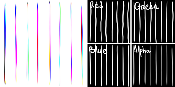
The solution to this is to also draw some shorter lines into our texture, and use the (screen space) length of each generated line to determine which to use. The specific implementation I chose, is to not just use the A channel of the image, but all four RGBA channels. The R channel is for the longest lines, up until the A channel that is used for the shortest lines.
float4 frag(g2f i) : SV_TARGET {
    float texture = i.id % 8;
    // This vector is one of (1,0,0,0), (0,1,0,0), etc, depending on
    // line length computed in the geometry shader (not shown).
    float4 channel_mask = float4(
                          i.size > 1,
        1    >= i.size && i.size > 0.5,
        0.5  >= i.size && i.size > 0.25,
        0.25 >= i.size
    );
    float2 uv = i.uv;
    uv.x = (uv.x + texture) * 0.125;

    // We later filter out just the channel we're interested in.
    float opacity = dot(tex2D(_MainTex, uv), channel_mask);
    return _LineColor * opacity;
}
Our lines texture now looks a bit messy, with each channel containing its own lines, but if you take a look at all channels separately, the texture still makes sense.
Finally, I also made this shader change the texture used every half a second, which is, just, vibes. Unity provides a _Time variable, so that’s a trivial change.
And with this, that’s everything there is to this shader!
I must emphasise, the performance is tragic
I must emphasise, the performance is tragic. (I must emphasise this.)
Just, on a fundamental level, every triangle of your mesh results in seven triangles being drawn by the GPU – one for the inner occlusion triangle, and six for the quads introduced. Now, this isn’t a shader that you would run on a high-poly mesh (your screen would just be a blob of colour) anyways, but it’s still a very large multiplying factor. It’s also painful that those six triangles are not made with tessellation (which GPUs are good at), but with geometry shaders.
Once I realised I didn’t care about performance, well, I stopped caring about performance. There’s tons of opportunities to optimise this shader, but if it’s fundamentally slow, and only to be used one time, why bother?
Note that this shader also usually puts two lines at every triangle edge, because triangles tend to be adjacent to each other. This only helps the hand-drawn effect as this gives more unique combinations of lines. This way it’s not “only” 32 possibilities for each line, but many more. But this also is a performance penalty, as drawing two lines per edge is pretty wasteful.
Conclusion
This is the adventure of how I went about creating a shader that’s so niche no-one is going to use it. But it was very interesting writing it! I like how this shader uses every single coordinate space you encounter over in graphics land:
- We shrunk the normals of the occluding pass in object space;
- We checked right angles in world space (although this could’ve also been possible in object space or camera space);
- We clipped our lines to the view frustum and viewport in camera space and screen space;
- And we finally drew our quads in screen space.
It’s not every day that you encounter a shader like this! Many shaders just have a magic step “go from object space to screen space”, and do something interesting mostly in the fragment stages. Or the interesting part is not the shader itself, but how it fits into a larger pipeline. But here, knowing something about all intermediate spaces is a requirement!
I hope that this is a good first post for my series of “I’m going to abuse my poor integrated GPU”, as there’s definitely more whacky shaders I’ve written and want to write about! As I mentioned in the introduction, both this shader, and a few other shaders, can be found in my pile-of-shaders repo.
footnotes and references
-
Of course, the history of graphics devices is much deeper than I make it seem here, and I’m wholly unqualified to talk about it anyways. ↩
-
Please don’t yell at me, graphics people. I know this is a ridiculous oversimplification. The slightly-less-ridiculous oversimplification comes a little later. ↩
-
I’m being facetious, it usually isn’t completely obvious what direction is “up”, whether you’re working in $[-1,1]^2$ or $[0,1]^2$, etc. etc. grumble, grumble. Sure, it’s not difficult and only takes a few macros to deal with, but let me rant about this. It’s an absolutely unnecessary extra layer of not-even-complexity, just annoyance. ↩
-
For me, y is up. The only 3D things I’ve used extensively are Unity and Minecraft. I can’t reasonably have z point upwards then, can I? ↩
-
I’m intentionally glossing over the difference between clip space and normalised device coordinates and everything that comes with that, as that’s a distinction I don’t want to discuss here. ↩
-
This is a completely subjective choice. Doing this causes detailed meshes further away to become small coloured blobs instead, which I don’t mind.
However, to someone else, this may be unacceptable, in which case you’d need different line thicknesses. Line thickness is a great way to highlight objects (thick outlines, thin inner lines), convey depth (thick lines close by, thin lines far away), shading (thicker lines in shaded areas), etc. I’m not an artist, though, and this is a programming blog, so I won’t go into this further than this footnote.
If you do want to use different line thicknesses, I’d still recommend doing this in screen space as I did with consistent thickness. The quads you generate should then be of different thickness, that’s all. The information you need for this (mostly normals and depth) lie at your fingertips, so that shouldn’t pose very many issues. ↩
-
See this stackexchange post for some discussion that also links to further reading.
There is also this in-depth older post (from 2015) that I have been taking as gospel. I don’t know how much of it still applies, but the following part is pretty troublesome:
The API requires that the output of a geometry shader be rendered in input order. The fixed-function hardware on the other side is required to consume geometry shader outputs serially. This creates a sync point.
Even if you know very little about GPUs at all, hearing the words “sync point” when working with millions of triangles… some red flags ought to be raised! ↩
-
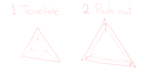
Tessellation shaders don’t work as well for the intuitive approach. I haven’t tried it, but they may very well work still. The idea is as follows: we tessellate our triangle so that we get one central inner triangle, and a bunch of other triangles. This inner triangle will grow to encompass a large region, while the other triangles will just not render anything at all. This requires “clever” (hacky) usage of the barycentric coordinates your tessellation shader is given.
This has much less overdraw; the winding order ensures that all triangles, except the large one, are culled. We do get a little more triangles, but at least these triangles were generated by tessellation, instead of geometry shaders, which is better.
Nevertheless, as I’ve emphasised countless times, this is really not a shader you’d want to run in any context in which performance matters. That’s why I haven’t implemented this theoretically better version – I simply don’t care about doing it like this. The geometry approach is just much more intuitive.
(Well, intuitive enough to write a post over half an hour long about, but…) ↩
-
Oh right, I didn’t mention the perspective division yet. Uhh… I’m not going to explain why the
p1 /= p1.wandp2 /= p2.wlines indraw_line()are a thing in this post, because I’d need to explain homogeneous coordinates for that, and I’d like you to build intuition and all that. This post is long enough as is…Just assume it’s a step we need to do to create perspective, and it’s the step that turns our sort-of pyramid-shaped frustum into a neat box.
(You may be wondering why we need to do this division after multiplying with
UNITY_MATRIX_Pin this geometry shader, but not in the earlier vertex shader in the “Occlusion” section. The answer: the hardware does it for you after the vertex shader, but we’re not in the vertex shader any more!) ↩ -
It would be slightly better to have the vertex shader convert to world space, but that’s bad for presentation purposes. ↩

